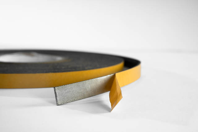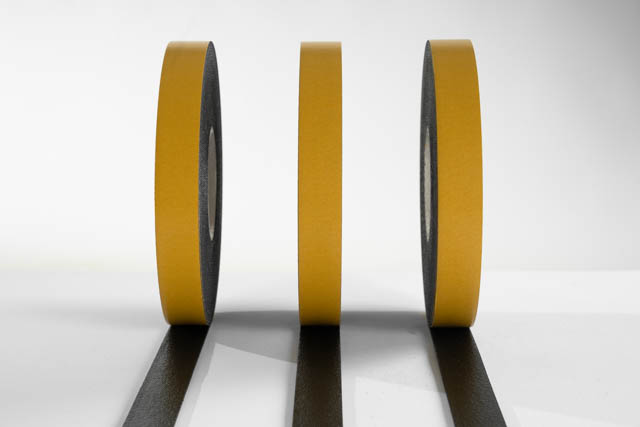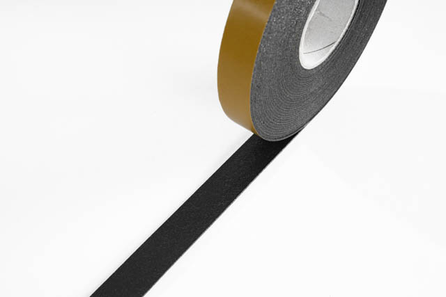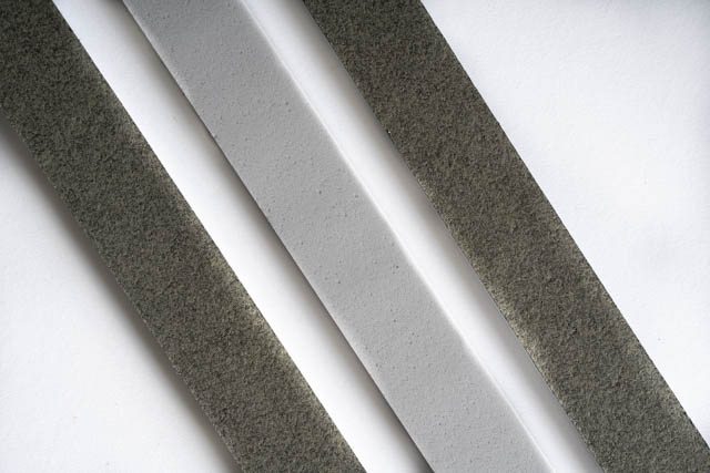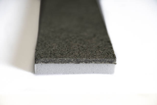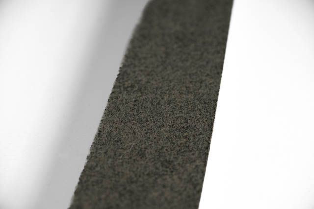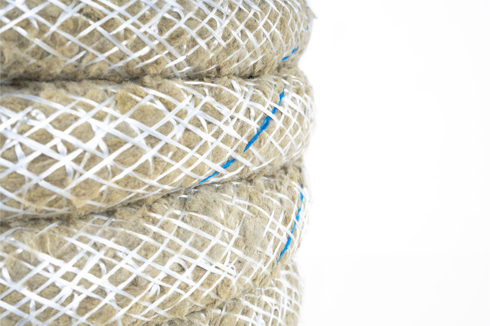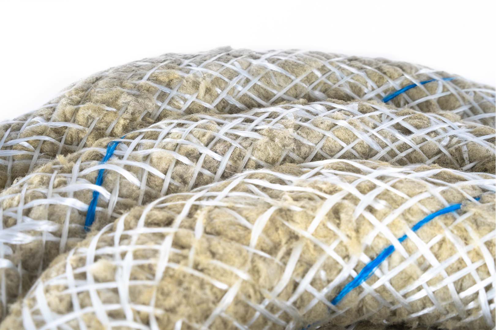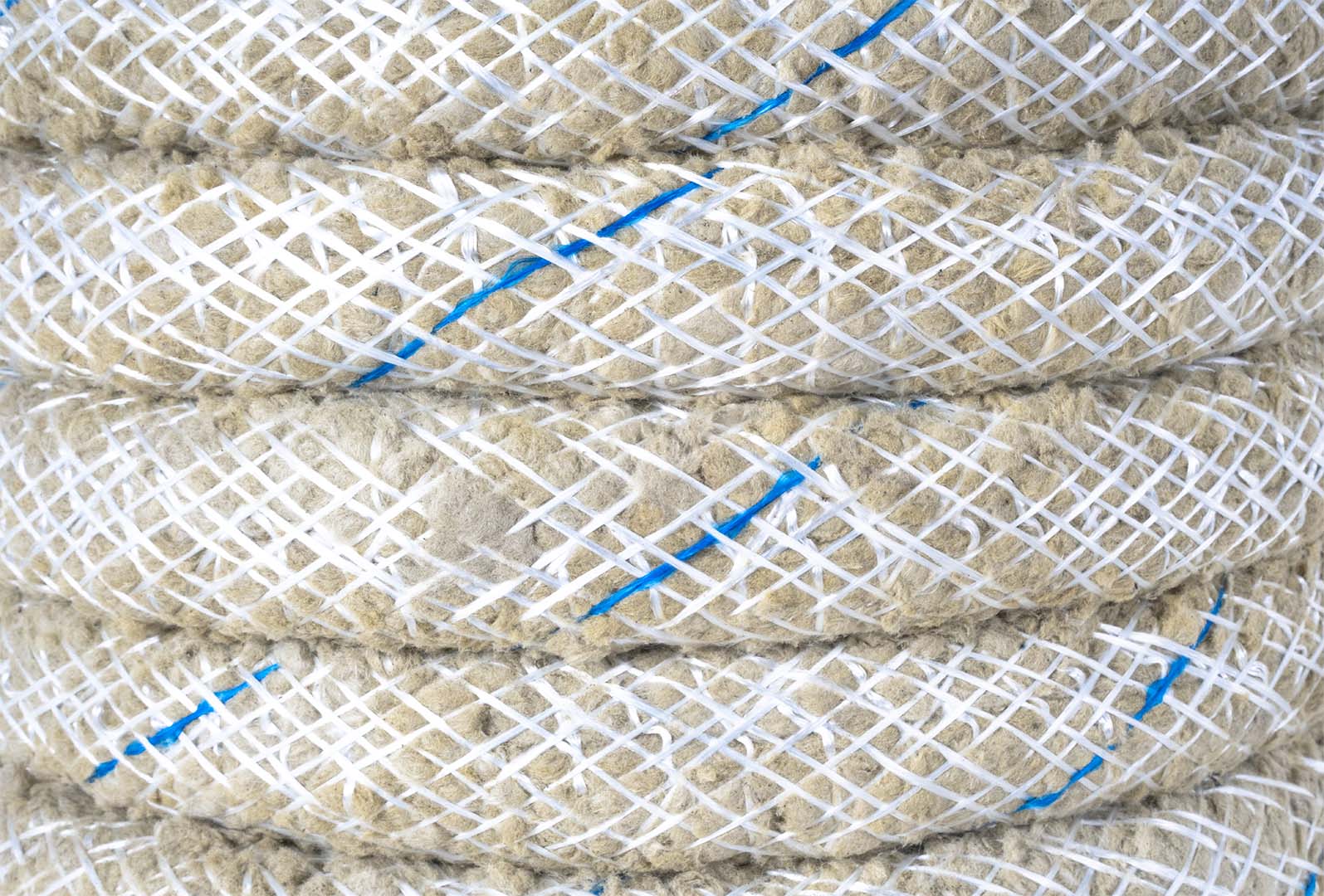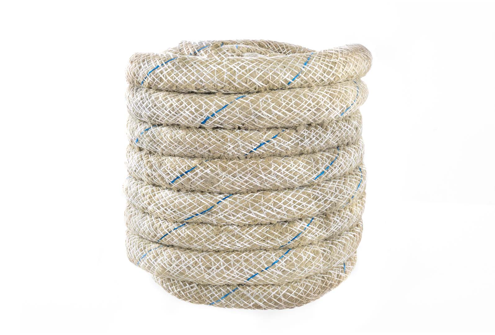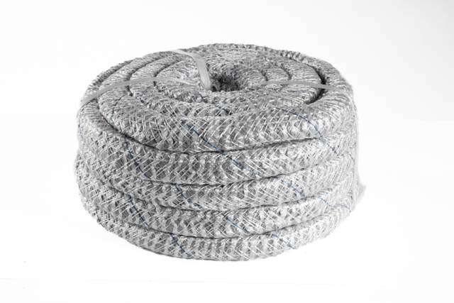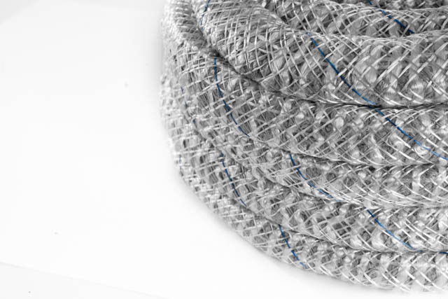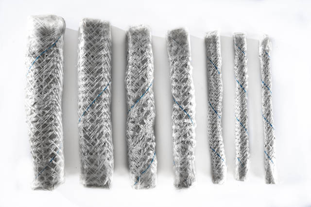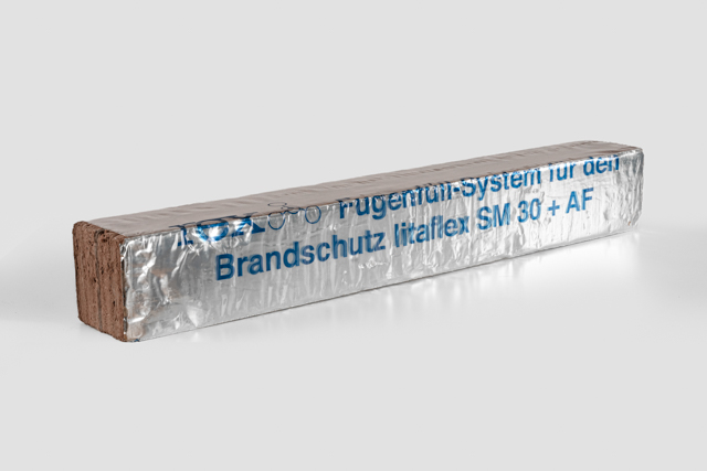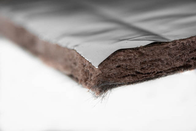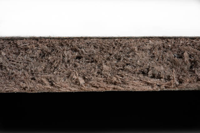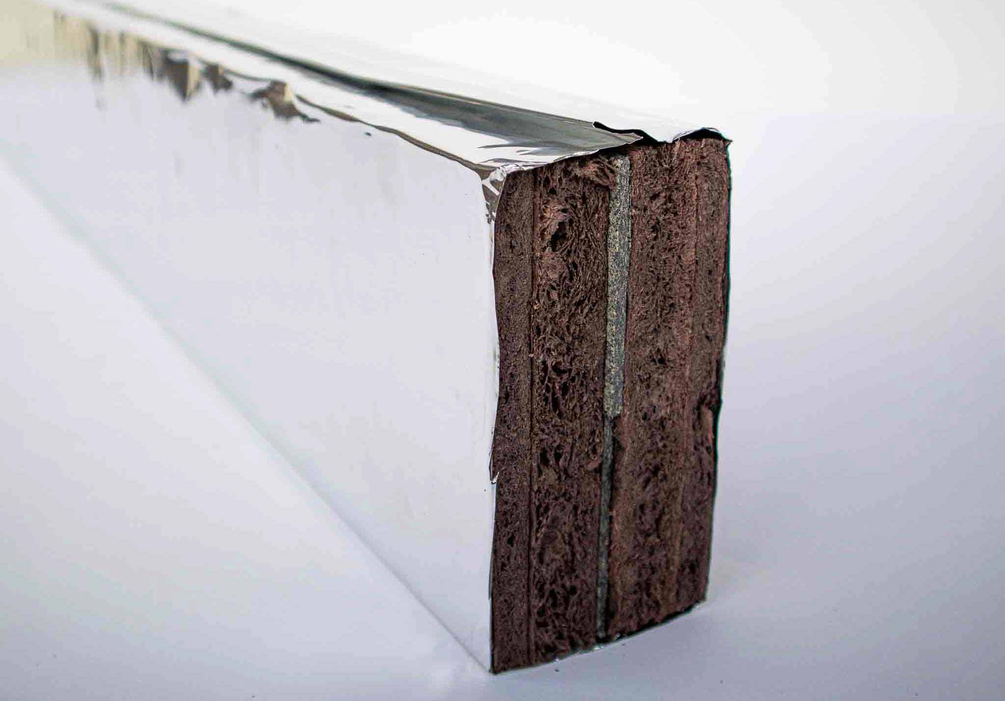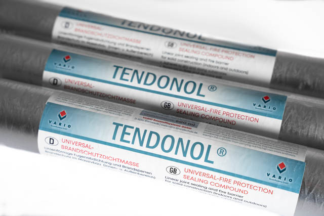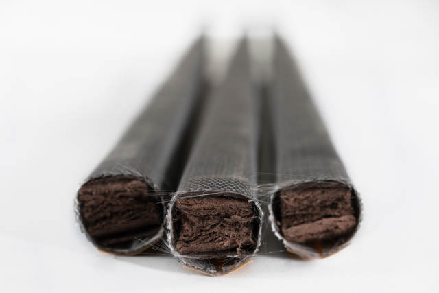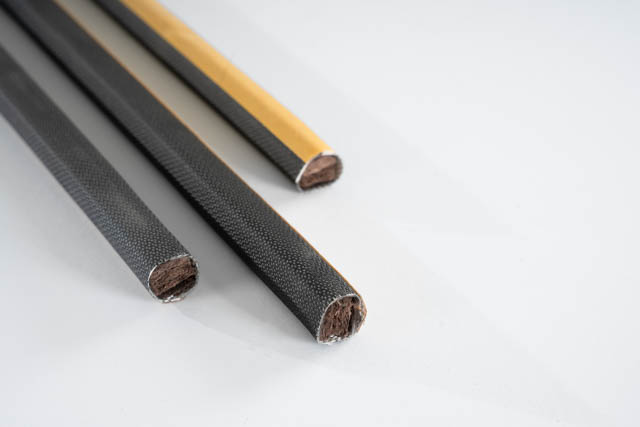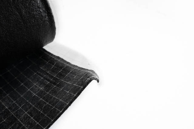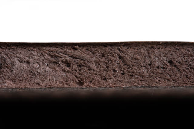

REX joint filling systems are non-combustible joint fillers or fire protection sealants according to DIN 4102-A1. or EN 13501-1. They are mainly deployed in expansion and movement joints in all areas of building construction, civil engineering, tunnel construction and industrial construction. Depending on their design, they prevent permissible temperatures from being exceeded for 30 to 180 minutes and prevent the passage of fire and flammable gases.
- * Fire protection for joints tested according to DIN 4102 and European standard EN 1366-4
Fire resistance: F 30 A, F 60 A, F 90 A, 120 A, F 180 A in walls and in ceilings (DIN 4102)
EI 90 -H-X-F-W00 up to 55 (EN 13501)
EI 90 -H-M65 (shear only) -F-W10 to 50 (EN 13501) (for joint areas with mechanically induced shear stress)
Building material class: A1 according to DIN 4102
A1 according to EN 13501-1
Joint widths: up to 55 mm
e.g.
EI 120-V-X-F-W 10 to 55
or
EI 120-H-M040-F-W 50
E Room closure
I Thermal insulation
120 Fire resistance duration in minutes
V vertical supporting structure (wall joint)
H horizontal supporting structure (ceiling joint)
X Mobility: no movement (max. permissible lateral movement 7.4 %)
M Mobility: maximum permissible movement in %.
F Butt joint created on site
W Range of joint widths from/to in mm
- Tested for joints between building components both with and without shear load. In the case of shear movement, the joints may have a shear movement of Delta h = 10 cm = 100 mm.
- Tested joint widths for joints without vertical shear stress up to 55 mm.
- Tested joint widths for joints with vertical shear stress up to 50 mm.
Combustible joint filler in the joint space not filled by the joint rope may remain in the joint. This means that combustible filler material in the joint must only be removed to the extent that space is required for the installation of the SG 300 Joint rope. Additional sealants to protect against dirt, water and destruction do not affect the fire behavior. Simple assembly without the need for elaborate aids.
Joints between structural members, which can be formed as step joints (multi-step joints), linear butt joints (single-step joints) and shear joints (see images).
- For shear joints, the shear movement may be up to 10 cm.
- Lateral expansion (joint widening) in a joint may not exceed 7.5% of the joint width.
- The joint seals are to be inserted between two parallel joint flanks. Deviations from parallelism are permissible if the largest joint gap dimension does not exceed the maximum permissible value of the joint
- width.
- The arrangement of the joint rope can generally be freely selected.
- If the joint ropes are arranged in several layers, the joints must be staggered by 500 mm.
- If joint ropes are butted, in joints with a width of w ≤ 30 mm, the butted joint ropes must have an overlap of at least 100 mm.
- In joints with a width of w > 30 mm, the joint ropes can be butted at the joints.
- Additional permanently elastic sealing of the joint with sealants or joint cover profiles is permissible!
- Combustible filling material or joint fillings do not have to be removed!
- Glueing in the joint rope with litaflex adhesive 800 is permitted!
- The dimensioning, as well as the number of layers of the joint rope to be installed, can be determined from Tables 1 and 2 depending on the required fire resistance class and the joint widths:
Joints without vertical shear stress
Joint width (mm) EI 90-V-X-F-W 10 up to 55 EI 90-H-X-F-W 10 up to 55 EI 120-V-X-F-W 55 EI 120-V-X-F-W 55
Installation case
Number of layers and arrangement Classification
(A) (B) 10 up to 55 1 any
(A) (B) 55 1
Overview of fire-resistant versions for installation in ≥ 100 mm thick solid walls and ≥ 150 mm thick solid ceilings with a gross density of ≥ 700 kg/m³.
Joints with vertical shear stress
Joint width (mm) 1 layer on both sides, distance a ≥ 25 mm to the outer edge of the component layers side by side without spacing, arrangement within the joint arbitrary EI 120-V-X-F-W 10 up to 55 EI 120-H-X-F-W 10 up to 55 EI 180-V-X-F-W 10 up to 55 EI 180-H-X-F-W 10 up to 55
Installation case
Number of layers and arrangement Classification
(A) (C) 10 up to 50 2
EI 90-H-M 65--F-W 10 up to 50
(A) (B) 10 up to 50 2
(A) (B) 10 up to 27
37 up to 554
3
Overview of fire-resistant versions for installation in ≥ 150 mm thick solid walls and ≥ 150 mm thick solid ceilings with an apparent density of ≥ 2400 kg/m³ ± 20 %.
-
up to55 mmJOINT WIDTH
-
PREVENTS FIRE PASSAGE UP TO180 min

Co-Division Manager/Sales Manager
HT Insulation/Fire Protection

Sales + Application technology
HT Insulation/Fire protection

